Author: Khanh Nguyen

  • MPM fracture CRAMP – Line crossing algorithm visualizer

    MPM fracture CRAMP – Line crossing algorithm visualizer

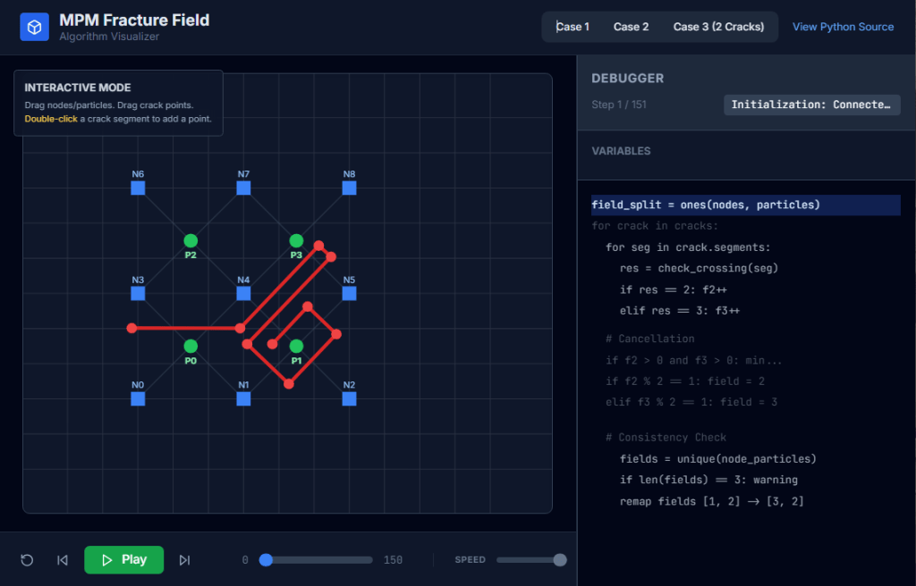
    Check my github: MPM Field Visualizer

    Line Crossing Algorithm:

    The most time consuming, new calculation required for CRAMP is the linecrossing calculation in Task 2. It is important for this calculation to be optimal and precise. The only numerical difficulty occurs when a node lies very close to the crack path. In some line-crossing algorithms, numerical round off in this situation could result in two particles on the same side of the crack being labeled as being on opposite sides. The complementary problem of when a material point lines very close to a crack path never occurs because the contact methods keep particles from reaching the crack path.

    A line-crossing algorithm in 2D based on signed areas of certain triangles solved the problem of nodes on cracks. For any three points, x1, x2, and x3, the signed area of the triangle with those vertexes is given by

    Area = x1(y2−y3)+x2(y3−y1)+x3(y1−y2) (33)

    This area is positive if the path from x1 to x3 is counter clockwise, negative if it is clockwise, and zero if the points are collinear. Using this signed area, the algorithm is as follows:

    Subtask 1:

    Before doing any calculations, determine if the rectangle defined by the particle (x1 = xp) and the node (x2 = xn) under consideration intersects the extent of the segment endpoints in the crack. If it does not, the line does not cross the crack and rest of the algorithm can be skipped for that crack.

    Subtask 2:

    For each crack segment with endpoints x3 and x4, calculate the sign of the areas of triangles (123), (124), (341), and (342) denoted as “+”, “−” or “0”.

    Subtask 3:

    The particle is above the crack if the signs are (−++−), (−++0), (0++0), or (−0+0). The first case is the most common; the other three correspond to the node being on the crack segment, on the start point of the crack segment, or on the end point of the crack segment, respectively. The cases where the material point is on the crack segment can be ignored. Similarly, the particle is below the crack if the signs are (+−−+), (+−−0), (0−−0), or (+0−0). All other combinations of signs indicate the line does not cross the line segment. In practice, many signed area calculations can be skipped. For example is the signs of (123) and (124) are (++), there is no need to evaluate the signs of (341) and (342) because the line can not cross the segment.

    Subtask 4:

    One complication is that a given xp to xn line might cross more than one segment in a single crack. In this situation, the crossing is ignored unless there are an odd number of crossings. To include this possibility, the previous two steps must check all segments in a crack before deciding if there is a crossing, but if Subtask 1 finds no intersection, the check for all segments in that crack can be skipped.

    — Nairn (2003)

    Particle-crack posision check:

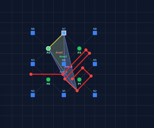
    Node-crack stability check. (Sub stack 4)

    <p id="<reference>Nairn-JA.-Material-point-method-calculations-with-explicit-cracks.-Comput-Model-Eng-Sci-2003;4:649–64.References:

    Nairn JA. Material point method calculations with explicit cracks. Comput Model Eng Sci 2003;4:649–64.

    Tito Adibaskoro, Stéphane Bordas, Wojciech T. Sołowski, Simo Hostikka,
    Multiple discrete crack initiation and propagation in Material Point Method, Engineering Fracture Mechanics, Volume 301, 2024, 109918, ISSN 0013-7944, https://doi.org/10.1016/j.engfracmech.2024.109918.

  • Create equation caption and referencing MSWord

    Create equation caption and referencing MSWord

    1. Manual

    Alt + = to trigger Equation Editor.

    Default Unicode mode.

    Type

    “<<Equation>>(#4.1)”

    Enter

    Result

    *Note: No cross-referencing available!!!

    2. Automatic and cross-referencing enable

    2.1. Table way

    • Insert 3 column table
    • Format it to remove all margin and no border. Center align the middle cell, left align the left and right align the right
    • Insert an example equation in middle cell and a citation in right cell
    • Select whole table > Insert > On the Insert tab, in the Text group, click Quick Parts, and then click Save Selection to Quick Part Gallery, change the name and add a description if you like, and click OK.
    • Assign a keyboard shortcut to the Quick Part via File > Options > Customize Ribbon > Customize. Choose the “Building Blocks” category in the dialog box and locate your entry. Use the “Press new shortcut key” box to assign the shortcut (e.g. Alt + Ctrl + =), and then click the Assign button.

    2.2. Style separator way

    • <Alt + => and type the equation
    • Make it right align or pre-define a Styles that right-align.
    • Enter the next line and Insert caption (<Alt><S><P>)
    • Place the cursor right at the end of equation and insert a Style separator <Ctrl+Alt+Enter>
    • Manually adjust the spacing for sophisticated purpose.

    2.3. Cross-referencing

    <Alt><S>(quick:<R><F>) -> Equation…

  • Custom Python Scripts for AutoCAD Plant 3D – Case study of tubing fittings – SCRIPT

    from varmain.primitiv import *
    from varmain.custom import *
     
    @activate(Group="Coupling", TooltipShort="Tube Male Connector TubexMPT", TooltipLong="Tube Male Connector TubexMPT", FirstPortEndtypes="P", LengthUnit="in",  Ports="2")
    @group("MainDimensions")
    @param(D=LENGTH, TooltipShort="Tube OD", TooltipLong="Tube OD")
    @param(D1=LENGTH, TooltipShort="Hex head OD", TooltipLong="Fitting hex head OD")
    @param(D31=LENGTH, TooltipShort="Hex OD of Body", TooltipLong="Hex OD of Body")
    @param(L=LENGTH, TooltipShort="Length of Fitting", TooltipLong="Overall Length of Fitting")
    @param(L31=LENGTH, TooltipShort="Tube gland", TooltipLong="Tube gland length")
    @param(I1=LENGTH, TooltipShort="Tube insert", TooltipLong="Tube insert distance")
    @param(OF=LENGTH0)
     
    #(arxload "PnP3dACPAdapter")
    #(testacpscript "maleConnector")
    def maleConnector(s, D=0.25, D1=0.5625, D31=1.0625, L=1.82, L31=0.6, I1=0, K=1, OF=0, **kw):
        #length
        L32 = L31*0.6 #adjusting the length of hex head
        L33 = L - L31 #adjusting the length of hex head
        L1 = 0.2 #adjusting the length of body
           
        #hex head
        headStartangle = 0
        headBox1 = BOX(s, L=D1, W=D1, H=L32).translate((L32/2,0,1.866*D1/2)).rotateX(headStartangle) #cos(30deg) = 0.866
        headBox2 = BOX(s, L=D1, W=D1, H=L32).translate((L32/2,0,1.866*D1/2)).rotateX(headStartangle+60) #cos(30deg) = 0.866
        headBox3 = BOX(s, L=D1, W=D1, H=L32).translate((L32/2,0,1.866*D1/2)).rotateX(headStartangle+2*60) #cos(30deg) = 0.866
        headBox4 = BOX(s, L=D1, W=D1, H=L32).translate((L32/2,0,1.866*D1/2)).rotateX(headStartangle+3*60) #cos(30deg) = 0.866
        headBox5 = BOX(s, L=D1, W=D1, H=L32).translate((L32/2,0,1.866*D1/2)).rotateX(headStartangle+4*60) #cos(30deg) = 0.866
        headBox6 = BOX(s, L=D1, W=D1, H=L32).translate((L32/2,0,1.866*D1/2)).rotateX(headStartangle+5*60) #cos(30deg) = 0.866
        headBox1.uniteWith(headBox2)
        headBox1.uniteWith(headBox3)
        headBox1.uniteWith(headBox4)
        headBox1.uniteWith(headBox5)
        headBox1.uniteWith(headBox6)
        headBox2.erase()
        headBox3.erase()
        headBox4.erase()
        headBox5.erase()
        headBox6.erase()
    
        head1 = CYLINDER(s, R=D1/2, H=L32, O=0).rotateY(90)
        head1.subtractFrom(headBox1)
        headBox1.erase()
    
        #body create
        bodyMain = CYLINDER(s, R=0.8*D1/2, H=L, O=0).rotateY(90)
    
        # hex head second
        head2Startangle = 0
        head2Box1 = BOX(s, L=D31, W=D31, H=L33*0.2).translate((L33*0.2/2+L31,0,1.866*D31/2)).rotateX(head2Startangle) #cos(30deg) = 0.866
        head2Box2 = BOX(s, L=D31, W=D31, H=L33*0.2).translate((L33*0.2/2+L31,0,1.866*D31/2)).rotateX(head2Startangle+60) #cos(30deg) = 0.866
        head2Box3 = BOX(s, L=D31, W=D31, H=L33*0.2).translate((L33*0.2/2+L31,0,1.866*D31/2)).rotateX(head2Startangle+2*60) #cos(30deg) = 0.866
        head2Box4 = BOX(s, L=D31, W=D31, H=L33*0.2).translate((L33*0.2/2+L31,0,1.866*D31/2)).rotateX(head2Startangle+3*60) #cos(30deg) = 0.866
        head2Box5 = BOX(s, L=D31, W=D31, H=L33*0.2).translate((L33*0.2/2+L31,0,1.866*D31/2)).rotateX(head2Startangle+4*60) #cos(30deg) = 0.866
        head2Box6 = BOX(s, L=D31, W=D31, H=L33*0.2).translate((L33*0.2/2+L31,0,1.866*D31/2)).rotateX(head2Startangle+5*60) #cos(30deg) = 0.866
        head2Box1.uniteWith(head2Box2)
        head2Box1.uniteWith(head2Box3)
        head2Box1.uniteWith(head2Box4)
        head2Box1.uniteWith(head2Box5)
        head2Box1.uniteWith(head2Box6)
        head2Box2.erase()
        head2Box3.erase()
        head2Box4.erase()
        head2Box5.erase()
        head2Box6.erase()
    
        head2 = CYLINDER(s, R=D31/2, H=L33*0.2, O=0).rotateY(90).translate((L31,0,0))
        head2.subtractFrom(head2Box1)
        head2Box1.erase()
    
        head2F = CONE(s, R1=D31/2*0.85, R2=D31/2*0.7, H=L33, E=0).rotateY(90).translate((L31,0,0))
        head2.uniteWith(head2F)
        head2F.erase()
    
        #joint 3 parts
        bodyMain.uniteWith(head1)
        bodyMain.uniteWith(head2)
        head1.erase()
        head2.erase()
    
        #create a hole fitting
        boreCy = CYLINDER(s, R=D/2, H=L, O=0).rotateY(90)
        bodyMain.subtractFrom(boreCy)
        boreCy.erase()
    
        #tube insert distance
        if I1 == 0:
            I1 = L31
        
        #set port points
        s.setPoint((0.0 + I1, 0.0, 0.0), (-1.0, 0.0, 0.0), 0)
        s.setPoint((L, 0.0, 0.0), (1.0, 0.0, 0.0), 0)
        
        return


    See PART 1:

    https://enginine.com/2025/11/11/custom-python-scripts-for-autocad-plant-3d-case-study-of-tubing-fittings-part-1/

  • Custom Python Scripts for AutoCAD Plant 3D – Case study of tubing fittings – PART 2

    After testing the script in PART 1, a geometry is created. Our job now is now publish it into the catalog.

    Image creation

    Manually dim all the necessary and changing CAD environment into white background (or any color)

    Capture the image using an app like PicPick or Cropper to create three images with different sizes: maleConnector_64.png maleConnector_200.png maleConnector_640.png with size 64×64, 200×200, 640×640 accordingly

    PART CREATION

    Final step is to launch Spec Editor. Open an existing CustomCatalog (better than a whole new catalog using CatalogBuilder). Choose “Create New Component” and choosing our part by selecting the group (defined in script).

    Setting and save the catalog. Now it ready-to-use in Plant3D.

    See PART 3:

    https://enginine.com/2025/11/11/custom-python-scripts-for-autocad-plant-3d-case-study-of-tubing-fittings-script/

  • Custom Python Scripts for AutoCAD Plant 3D – Case study of tubing fittings – PART 1

    Let’s try a simple male connector. First, we’ll grasp a drawing from Swagelok as reference:

    Coding

    We import libraris in the header, then define part’s principal dimensions which used to drive the entire model, serving as user inputs:

    from varmain.primitiv import *
    from varmain.custom import *
     
    @activate(Group="Coupling", TooltipShort="Tube Male Connector TubexMPT", TooltipLong="Tube Male Connector TubexMPT", FirstPortEndtypes="P", LengthUnit="in",  Ports="2")
    @group("MainDimensions")
    @param(D=LENGTH, TooltipShort="Tube OD", TooltipLong="Tube OD")
    @param(D1=LENGTH, TooltipShort="Hex head OD", TooltipLong="Fitting hex head OD")
    @param(D31=LENGTH, TooltipShort="Hex OD of Body", TooltipLong="Hex OD of Body")
    @param(L=LENGTH, TooltipShort="Length of Fitting", TooltipLong="Overall Length of Fitting")
    @param(L31=LENGTH, TooltipShort="Tube gland", TooltipLong="Tube gland length")
    @param(I1=LENGTH, TooltipShort="Tube insert", TooltipLong="Tube insert distance")
    @param(OF=LENGTH0)
    

    Define the function:

    def maleConnector(s, D=0.25, D1=0.5625, D31=1.0625, L=1.82, L31=0.6, I1=0, K=1, OF=0, **kw):
    

    As AutoCAD Plant 3D (PLNT3D) only accept a few primitives, we have to being creative in our coding part.

    Hex nut shape will be treat as a cylinder being trimmed by six cubes, then delete these cubes away:

        #hex head
        headStartangle = 0
        headBox1 = BOX(s, L=D1, W=D1, H=L32).translate((L32/2,0,1.866*D1/2)).rotateX(headStartangle) #cos(30deg) = 0.866
        headBox2 = BOX(s, L=D1, W=D1, H=L32).translate((L32/2,0,1.866*D1/2)).rotateX(headStartangle+60) #cos(30deg) = 0.866
        headBox3 = BOX(s, L=D1, W=D1, H=L32).translate((L32/2,0,1.866*D1/2)).rotateX(headStartangle+2*60) #cos(30deg) = 0.866
        headBox4 = BOX(s, L=D1, W=D1, H=L32).translate((L32/2,0,1.866*D1/2)).rotateX(headStartangle+3*60) #cos(30deg) = 0.866
        headBox5 = BOX(s, L=D1, W=D1, H=L32).translate((L32/2,0,1.866*D1/2)).rotateX(headStartangle+4*60) #cos(30deg) = 0.866
        headBox6 = BOX(s, L=D1, W=D1, H=L32).translate((L32/2,0,1.866*D1/2)).rotateX(headStartangle+5*60) #cos(30deg) = 0.866
        headBox1.uniteWith(headBox2)
        headBox1.uniteWith(headBox3)
        headBox1.uniteWith(headBox4)
        headBox1.uniteWith(headBox5)
        headBox1.uniteWith(headBox6)
        headBox2.erase()
        headBox3.erase()
        headBox4.erase()
        headBox5.erase()
        headBox6.erase()
    
        head1 = CYLINDER(s, R=D1/2, H=L32, O=0).rotateY(90)
        head1.subtractFrom(headBox1)
        headBox1.erase()
    

    After create other shapes, we combine them into one body:

        #joint 3 parts
        bodyMain.uniteWith(head1)
        bodyMain.uniteWith(head2)
        head1.erase()
        head2.erase()
    

    Create insert point and port points. As tube will penetrate these fittings in tubing port, we have to offset one port inwardy:

        #tube insert distance
        if I1 == 0:
            I1 = L31
        
        #set port points
        s.setPoint((0.0 + I1, 0.0, 0.0), (-1.0, 0.0, 0.0), 0)
        s.setPoint((L, 0.0, 0.0), (1.0, 0.0, 0.0), 0)
    

    Code Testing

    Choose Share Content folder by command MODIFYSHAREDCONTENTFOLDER or use default location (C:\AutoCAD Plant 3D 2016 Content\CPak Common\CustomScripts). Save script file at that location.

    Command PLANTREGISTERCUSTOMSCRIPTS to compiled the script. Load PnP3dACPAdapter.arx by arxload "PnP3dACPAdapter".

    Test the script by testacpscript "maleConnector".

    Note: If any modification, PLNT3D must be closed, then register script again.

    See PART 2:

  • Plant3D Database PnPID, GUID vs

    • GUID (Globally Unique Identifier)
    • PnPID is a numeric, sequential ID that is unique within a specific project and spec (not necessarily globally unique)
    GUID is a 128-bit value, typically displayed as 32 hexadecimal digits, which is so large that the probability of the same number being generated twice is negligible. This uniqueness is crucial for ensuring a stable link between the spec and catalog files

    The Model-Spec Connection

    To understand how PnPID works, it’s important to distinguish between its use in the spec file and its use in the project’s 3D model database:

    • PnPID in the Spec: When you add a component part to a piping spec using the Spec Editor, that part is automatically assigned a new, unique PnPID. This ID is stored in the spec’s database file (.pspc).
    • PnPID and SpecRecordID in the Model: When you place that component from the spec into a 3D model, the component in the model is assigned its own unique PnPID within the project database. To maintain the link back to the spec, this model component also stores the original PnPID from the spec. This stored value is called the SpecRecordID.

    As shown in the database diagrams, the SpecRecordID in the project database (for example, in the Flange_PNP view) directly corresponds to the PnPID in the spec database. This creates a “one-to-many” relationship, where a single part entry in a spec (with one PnPID) can be linked to many instances of that part in the 3D models.

    Is PnPID Created per Item Family or per Size?

    The sources indicate that a PnPID is created for each individual part entry added to a spec, which effectively means it is created per size, not per item family.

    • The software automatically generates a new PnPID each time a part is added to a spec.
    • When building a spec, you typically add a component family (e.g., “Gate Valve, Conduit, 150 LB, RF”) from a catalog for a specific range of sizes. Each size becomes a separate record, or row, in the spec database.
    • Since each part added gets a new PnPID, a 2-inch valve and a 4-inch valve from the same family will be treated as separate parts in the spec and will therefore be assigned different, unique PnPID numbers.

    Deleting a part from a spec permanently breaks this connection for any associated 3D model parts because the PnPID is removed, and even re-adding the same part will generate a new, different PnPID. This highlights the importance of the PnPID being unique to each specific part entry (i.e., each size) within the spec.

    SizeRecordID?

    SizeRecordID is a Globally Unique Identifier (GUID)

    Link a specific part (including its size) from a catalog to its corresponding entry in a spec

    The Impact of Losing a SizeRecordID

    A new SizeRecordID is generated when a new component is added to a catalog. Because the SizeRecordID is the key that links a spec part back to its catalog origin, any action that changes this ID breaks the connection.

    For instance, if you delete a part from a spec and then add the “same” part back from the catalog, the new spec entry will have the same SizeRecordID as the catalog part, but you will have broken the link for any existing 3D model components, because that action will have created a new PnPID for the spec part.

    It is not possible to recover a lost SizeRecordID connection for a part. The recommended best practice is to never delete items from a spec if they are already in use in a model. Instead, you should modify the description to mark it as obsolete (e.g., “OUT OF SPEC“) and then use the PLANTSPECUPDATECHECK command and Data Manager to find and replace the “orphaned” parts in the model with a valid substitute

    Reference

    handout_11136_OG11136_20-_20_20AutoCAD_20Plant_203D_20Specs_20and_20Catalogs_20How_20to_20Create_20Unbreakable_20Project_20Workflows.pdf

  • TcHMI show case of a Vibration monitoring system

    A turbine pump using analogue sensors for winding and bearing temperature, keyphasor for rotating speed and velocity sensors for vibrating. The program is an implementation of TE2000 and TwinCAT 3, with custom Fourier function (just in case the sensors are not RMS).

    Go around main pages:

    Component detail value and data can be monitored / modified quickly via pop-up.

    Other features:

    Some features only work on real hardware. Video of working HMI on-site is prohibited.

    Source: https://github.com/KowalskiPi/Tc3_VN001007_VMS

  • The first installation of TC/BSD on touch panel Embeded IPC, TcHmi TF2000 and Client

    Hardware info

    CP6706-0001-0050
    Display size/resolution	7" 800 x 480
    Touch screen		single-finger touch screen
    Processor		Intel Atom® E3827, 1.75 GHz, 2 core
    Memory			8GB DDR3L RAm
    Hard disks/flash	40 GB CFast
    Interfaces		4 x USB 2.0, 1 x DVI
    Power supply		24 V DC

    Install X environments

    // Install Xorg
    $ pkg install xorg
    
    // Add a user into video user group
    $ doas pw groupmod video -m Aministrator
    
    // Get VGA info
    $ pciconf -lv|grep -B4 VGA
    // return: "Intel"...
    
    // Get input devices info
    // In X terminal
    $ doas libinput list-devices 
    // return: ELO Touch input device "dev/input/event3"


    Pass these generated info into config files.

    Install GUI windows

    // Unblock FreeBSD reposity
    $ doas ee /usr/local/etc/pkg/repos/FreeBSD
    $ >> FreeBSD: ( enable: yes )
    
    // Install openbox
    $ doas pkg install openbox
    
    // Install lightdm
    $ doas pkg install lightdm lightdm-gtk-greeter
    
    // Install on-screen keyboard to input password at hello screen
    $ doas pkg install florence
    
    $ doas ee /usr/local/etc/lightdm/lightdm.conf
    $ >> xserver-command=X -nocursor
    
    $ doas ee /usr/local/etc/lightdm/lightdm-gtk-greeter.conf
    $ >> keyboard= florence --focus
    $ >> keyboard-position= "75%,center -0;50%, 25%"
    
    // Follow config file to enable auto start boot into GUI instead of terminal environment
    

    Config files

    /usr_local_etc_X11_xorg.conf.d

    • 10-intel.conf.txt
    Section "Device"
            Identifier      "Card0"
            Driver          "modesetting"
    EndSection
    Section "Monitor"
            Identifier      "HDMI-2"
            VendorName      "ELOTouch"
            ModelName       "Monitor0Model"
            Option          "DPMS" "false"
    EndSection
    Section "Screen"
            Identifier      "Screen0"
            Device          "Card0"
            Monitor         "HDMI-2"
            SubSection      "Display"
            Modes           "800x480"
            EndSubSection
    EndSection
    Section "InputClass"
            Identifier "touchpad"
            MatchIsTouchPad "on"
            Driver  "libinput"
            Option  "Tapping" "on"
            Option  "NaturalScrolling"      "on"
    EndSection
    Section "InputClass"
            Identifier      "touchScreen"
            MatchIsTouchscreen      "on"
            Driver  "libinput"
            Option  "Device" "/dev/input/event3"
    EndSection
    Section "Files"
            FontPath "/usr/local/share/fonts/urwfonts/"
            FontPath "/usr/local/share/fonts/TrueType/"
    EndSection

    /boot/loader.conf.txt

    kern.geom.label.disk_ident.enable="0"
    kern.geom.label.gptid.enable="0"
    cryptodev_load="YES"
    zfs_load="YES"
    hint.attimer.0.clock="0"
    cuse_load="YES"
    hw.psm.synaptics_support=1
    usbhid_load="yes"
    hw.usb.usbhid.enable=1
    kldload i915kms
    hw.vga.textmode=1
    fdescfs_load="yes"

    /etc

    • fstab.txt
    do# Device                Mountpoint      FStype  Options         Dump    Pass#
    /dev/gpt/efiboot0               /boot/efi       msdosfs rw              2       2
    /dev/ada0p2             none    swap    sw              0       0
    proc                    /proc           procfs  rw              0       0
    fdescfs                 /dev/fd         fdescfs rw              0       0
    • rc.conf.txt
    #fonts_setting----------
    allscreens_flags="-f vgarom-thin-8x16"
    #####################
    zfs_enable="YES"
    dumpdev="AUTO"
    CXID_enable="YES"
    MDPService_enable="YES"
    ntpd_enable="YES"
    pf_enable="YES"
    TcSystemService_enable="YES"
    runonce_enable="YES"
    sendmail_enable="NO"
    sendmail_submit_enable="NO"
    sendmail_outbound_enable="NO"
    sendmail_msp_queue_enable="NO"
    dhcpcd_enable="YES"
    #ifconfig_igb0="inet 192.168.137.137 netmask 255.255.255.0"
    #defaultrouter="192.168.137.1"
    #ifconfig_igb1="dhcp"
    #dhcpcd_flags="--waitip --denyinterfaces igb0"
    dhcpcd_flags="--waitip"
    allscreens_kbdflags="-b quiet.off"
    syslogd_flags="-ss"
    devfs_system_ruleset="allow_usb_mount"
    hostname="CP-5B3CCE"
    
    #DAEMONS----------------------------
    zfs_enable="YES"
    #moused_enable="YES"
    webcamd_enable="YES"
    dbus_enable="YES"
    kld_list="i915kms"
    #gdm_enable="YES"
    lightdm_enable="yes"
    
    #RemoteDesktop----------------------
    sshd_enable="yes"
    xrdp_enable="yes"
    xrdp_sessman_enable="yes"
    
    #gateway_enable="true"
    
    #TcHmi------------------------------
    TcHmiSrv_enable="YES"
    • ttys.txt
    # name  getty                           type    status          comments
    #
    console none                            unknown off secure
    #
    ttyv0   "/usr/libexec/getty Pc"         xterm   onifexists secure
    # Virtual terminals
    //....existing ttyv
    ttyv8   "/usr/local/bin/xdm -nodaemon"  xterm   onifexists secure

    Enable TF2000

    // Install and enable HMI service
    $ doas pkg install TF2000-HMI-Server
    
    // Unblock firewall
    $ doas service pf stop
    
    $ doas ee /etc/pf.conf
    $ >> pass in quick proto tcp to port 0000 keep state
    $ >> pass in quick proto tcp to port 1010 keep state
    $ >> pass in quick proto tcp to port 1020 keep state
    $ >> pass in quick proto tcp to port 8080 keep state
    
    $ doas service pf start
    
    // Enable HMI service
    $ doas service TcHmiSrv start
    
    /// Remember add this line to rc.conf file above
    /// >> TcSystemService_enable="YES"
    
    /// Remember add this line to fstab.txt file also
    /// >> /dev/gpt/efiboot0               /boot/efi       msdosfs rw              2       2
    /// >> /dev/ada0p2             none    swap    sw              0       0
    
    // Install and config SQLite server
    $ doas pkg install sqlite
    
    // Change directory to
    $ cd /usr/local/etc/TwinCAT/Functions/TF2000-Hmi-Server/service/TcHmiProject
    // Change sqlite database as you like
    $ doas sqlite storage.db
    ...
    

    Install Firefox and enable kiosk mode to boot to HMI

    // Install firefox
    $ doas pkg install firefox
    
    // Edit autostart file
    $ doas ee /home/SystemUser/.config/openbox/autostart.sh
    $ >> 
    $ >> #!/bin/sh
    
    $ >> firefox --kiosk --private-window localhost:1010
    $ >> xset dpms 0 0 0
    $ >> xset s noblank
    $ >> xset s off
    
    // Run
    $ chmod +x /home/SystemUser/.config/openbox/autostart.sh

    Reposity

    See more at: