from varmain.primitiv import *
from varmain.custom import *
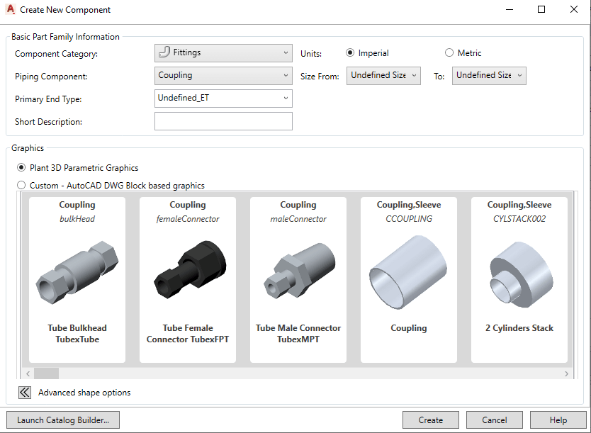
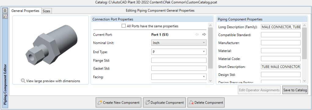
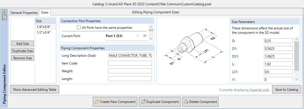
@activate(Group="Coupling", TooltipShort="Tube Male Connector TubexMPT", TooltipLong="Tube Male Connector TubexMPT", FirstPortEndtypes="P", LengthUnit="in", Ports="2")
@group("MainDimensions")
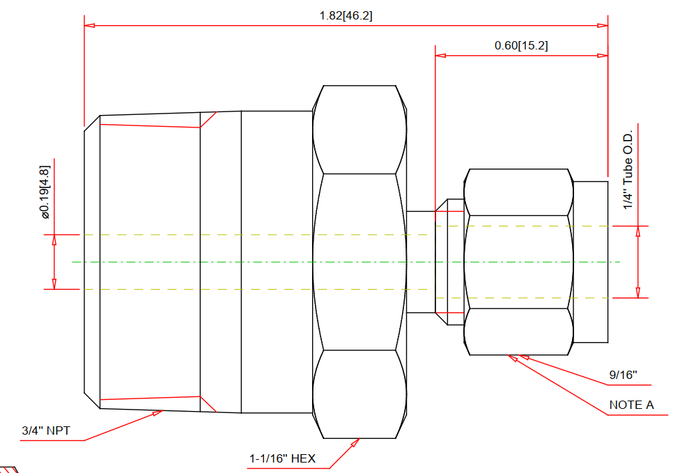
@param(D=LENGTH, TooltipShort="Tube OD", TooltipLong="Tube OD")
@param(D1=LENGTH, TooltipShort="Hex head OD", TooltipLong="Fitting hex head OD")
@param(D31=LENGTH, TooltipShort="Hex OD of Body", TooltipLong="Hex OD of Body")
@param(L=LENGTH, TooltipShort="Length of Fitting", TooltipLong="Overall Length of Fitting")
@param(L31=LENGTH, TooltipShort="Tube gland", TooltipLong="Tube gland length")
@param(I1=LENGTH, TooltipShort="Tube insert", TooltipLong="Tube insert distance")
@param(OF=LENGTH0)
#(arxload "PnP3dACPAdapter")
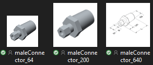
#(testacpscript "maleConnector")
def maleConnector(s, D=0.25, D1=0.5625, D31=1.0625, L=1.82, L31=0.6, I1=0, K=1, OF=0, **kw):
#length
L32 = L31*0.6 #adjusting the length of hex head
L33 = L - L31 #adjusting the length of hex head
L1 = 0.2 #adjusting the length of body
#hex head
headStartangle = 0
headBox1 = BOX(s, L=D1, W=D1, H=L32).translate((L32/2,0,1.866*D1/2)).rotateX(headStartangle) #cos(30deg) = 0.866
headBox2 = BOX(s, L=D1, W=D1, H=L32).translate((L32/2,0,1.866*D1/2)).rotateX(headStartangle+60) #cos(30deg) = 0.866
headBox3 = BOX(s, L=D1, W=D1, H=L32).translate((L32/2,0,1.866*D1/2)).rotateX(headStartangle+2*60) #cos(30deg) = 0.866
headBox4 = BOX(s, L=D1, W=D1, H=L32).translate((L32/2,0,1.866*D1/2)).rotateX(headStartangle+3*60) #cos(30deg) = 0.866
headBox5 = BOX(s, L=D1, W=D1, H=L32).translate((L32/2,0,1.866*D1/2)).rotateX(headStartangle+4*60) #cos(30deg) = 0.866
headBox6 = BOX(s, L=D1, W=D1, H=L32).translate((L32/2,0,1.866*D1/2)).rotateX(headStartangle+5*60) #cos(30deg) = 0.866
headBox1.uniteWith(headBox2)
headBox1.uniteWith(headBox3)
headBox1.uniteWith(headBox4)
headBox1.uniteWith(headBox5)
headBox1.uniteWith(headBox6)
headBox2.erase()
headBox3.erase()
headBox4.erase()
headBox5.erase()
headBox6.erase()
head1 = CYLINDER(s, R=D1/2, H=L32, O=0).rotateY(90)
head1.subtractFrom(headBox1)
headBox1.erase()
#body create
bodyMain = CYLINDER(s, R=0.8*D1/2, H=L, O=0).rotateY(90)
# hex head second
head2Startangle = 0
head2Box1 = BOX(s, L=D31, W=D31, H=L33*0.2).translate((L33*0.2/2+L31,0,1.866*D31/2)).rotateX(head2Startangle) #cos(30deg) = 0.866
head2Box2 = BOX(s, L=D31, W=D31, H=L33*0.2).translate((L33*0.2/2+L31,0,1.866*D31/2)).rotateX(head2Startangle+60) #cos(30deg) = 0.866
head2Box3 = BOX(s, L=D31, W=D31, H=L33*0.2).translate((L33*0.2/2+L31,0,1.866*D31/2)).rotateX(head2Startangle+2*60) #cos(30deg) = 0.866
head2Box4 = BOX(s, L=D31, W=D31, H=L33*0.2).translate((L33*0.2/2+L31,0,1.866*D31/2)).rotateX(head2Startangle+3*60) #cos(30deg) = 0.866
head2Box5 = BOX(s, L=D31, W=D31, H=L33*0.2).translate((L33*0.2/2+L31,0,1.866*D31/2)).rotateX(head2Startangle+4*60) #cos(30deg) = 0.866
head2Box6 = BOX(s, L=D31, W=D31, H=L33*0.2).translate((L33*0.2/2+L31,0,1.866*D31/2)).rotateX(head2Startangle+5*60) #cos(30deg) = 0.866
head2Box1.uniteWith(head2Box2)
head2Box1.uniteWith(head2Box3)
head2Box1.uniteWith(head2Box4)
head2Box1.uniteWith(head2Box5)
head2Box1.uniteWith(head2Box6)
head2Box2.erase()
head2Box3.erase()
head2Box4.erase()
head2Box5.erase()
head2Box6.erase()
head2 = CYLINDER(s, R=D31/2, H=L33*0.2, O=0).rotateY(90).translate((L31,0,0))
head2.subtractFrom(head2Box1)
head2Box1.erase()
head2F = CONE(s, R1=D31/2*0.85, R2=D31/2*0.7, H=L33, E=0).rotateY(90).translate((L31,0,0))
head2.uniteWith(head2F)
head2F.erase()
#joint 3 parts
bodyMain.uniteWith(head1)
bodyMain.uniteWith(head2)
head1.erase()
head2.erase()
#create a hole fitting
boreCy = CYLINDER(s, R=D/2, H=L, O=0).rotateY(90)
bodyMain.subtractFrom(boreCy)
boreCy.erase()
#tube insert distance
if I1 == 0:
I1 = L31
#set port points
s.setPoint((0.0 + I1, 0.0, 0.0), (-1.0, 0.0, 0.0), 0)
s.setPoint((L, 0.0, 0.0), (1.0, 0.0, 0.0), 0)
return
See PART 1: